


Installation, debugging and technology of programmable fountain equipment
Publish Time:2020/04/10 NEWS Number of views:1997
Requirements for installation and commissioning of programmable fountain equipment:
1. Pipeline and equipment installation: pipeline installation and water pump fixing.
The pipeline should be cleaned before installation, the main pipe should be horizontal, the vertical pipe should be vertical and the main pipe should be fixed; before the pipeline is painted with anti-rust paint, the rust and welding slag should be removed; the pump installation should be firm and stable.
2. Lighting installation: Fixture positioning, making and installing light clips, fixing fixtures.
3. Laying of cables and waterproof connection: the cables of pumps and lamps are routed according to the regulations, and the principle of reducing underwater joints is to connect with the cable (imported heat-shrinkable tube is waterproof), the cable is penetrated into the cable tube, the cable tube horn Glue seals, pumps and lamp wires are numbered according to the figure, and the cables are laid in the control room through the pipe or along the cable trench, and then enter the power distribution cabinet through the cable bridge.
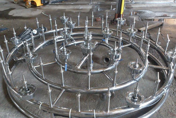
Program-controlled fountain equipment
A The performance of water pumps, valves and lighting fixtures must be tested before installation to ensure their integrity. The insulation resistance of the pump is measured by rocking, and its resistance should be greater than 50 megohms.
B The connection wire from the pool well to the pump and valve must use a jointless waterproof cable. The wire connection must be firm.
C The wires of lighting fixtures must be waterproof cables. The joints should be waterproofed according to the specified process, and the connection must be firm.
D Use a megohm meter to test the insulation resistance of each channel, which should be more than 5 megohms.
E Check whether the ground wires of the pump and the lamp are connected.
4. Installation of power distribution control equipment: control and power distribution equipment are in place in the control room according to the figure, and the load equipment is connected to the corresponding terminal of the electrical equipment according to the cable number.
5. All fountain electrical equipment (including: water pumps, lamps, electrical control cabinets, computers, controllers, inverters, transformers and other metal shells) must have equipotential grounding.
A The total equipotential bonding shall be provided with a terminal block in the incoming electrical control cabinet to connect the following conductive parts to each other:
(1) PE (PEN) busbar of incoming electrical control cabinet;
(2) The ground electrode of the control room;
B There is a local equipotential bonding terminal board in the fountain pool to connect the following conductive parts to each other;
(1) Metal shell of water pump and lighting fixtures;
(2) Metal pipes for water supply, drainage and overflow;
C All fountain electrical equipment (including: electric control box, computer, controller, frequency converter, transformer and other metal shells) must have auxiliary equipotential connection;
D The total equipotential bonding plate (ground row) and the local equipotential bonding terminal board are made of copper plates, and the total equivalence connection line is not less than 0.5X PE line cross section. The cross section of the auxiliary equipotential bonding wire is not less than 4.0 square millimeters of copper wire or 8mm diameter round steel or 20X4mm flat steel.
E The connection between the connecting conductors in the equipotential bonding can be welded or bolted. The overlapping length of the flat steel shall not be less than 2 times its width, and it shall be welded on three sides. The lap length of round steel should not be less than 6 times its diameter, and double-sided welding is used.
F The equipotential bonding wire should have a yellow-green color code. The equipotential bonding terminal board should be painted with yellow primer and marked with black marks.
G For concealed and connected county party committee connecting lines and their joints, construction personnel should make hidden inspection records and inspection reports.
H Conduct the continuity test after installing the equipotential bonding. The test voltage is a direct / AC 24V power supply, and the test current is greater than 0.2A. The resistance between the equipotential bonding terminal board and the metal ends in the entire equipotential bonding range is not greater than 0.5 ohm.
- The role of water curtain fountain and cla...
- musical fountain contractor selection
- Talking about the Influence of Music Fount...
- The choice of music fountain manufacturers...
- The fountain company tells you what you ne...
- Fountain design company is how to control ...
- What are the types of fountains?
- immersive water experience design


